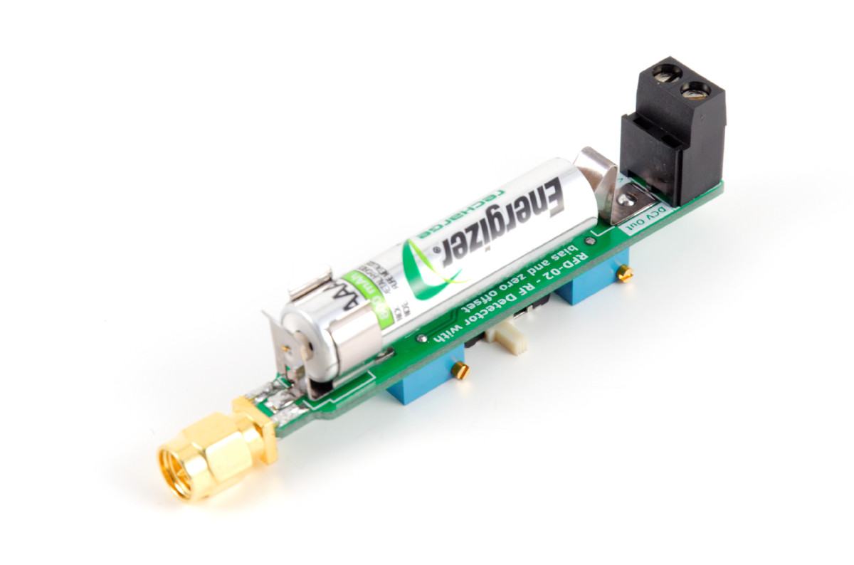
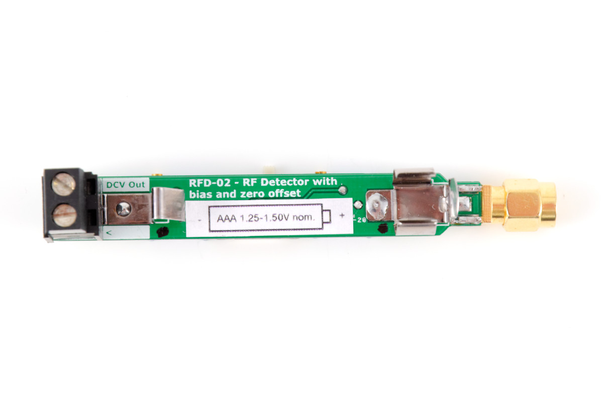
RF Detector with Offset and Zero - SMA - RFD-BIAS

Released: March 2014 - rev3
Want to find out how good your antenna is performing? This is a sensentive and accurate high frequency RF detector. It can be used as part of a system to measure the effiency of an antenna.
Compared to the simpler RDF-01 RF Detector, this has a bias adjustment. With DC bias the detector input impedance is reduced significantly for low power transmitters and most of the input power is detected over the output (load) instead. This makes it work more like a RF receiver which boosts sensitivity and dynamic range/resolution. It improves sensitivity with about 12dB.
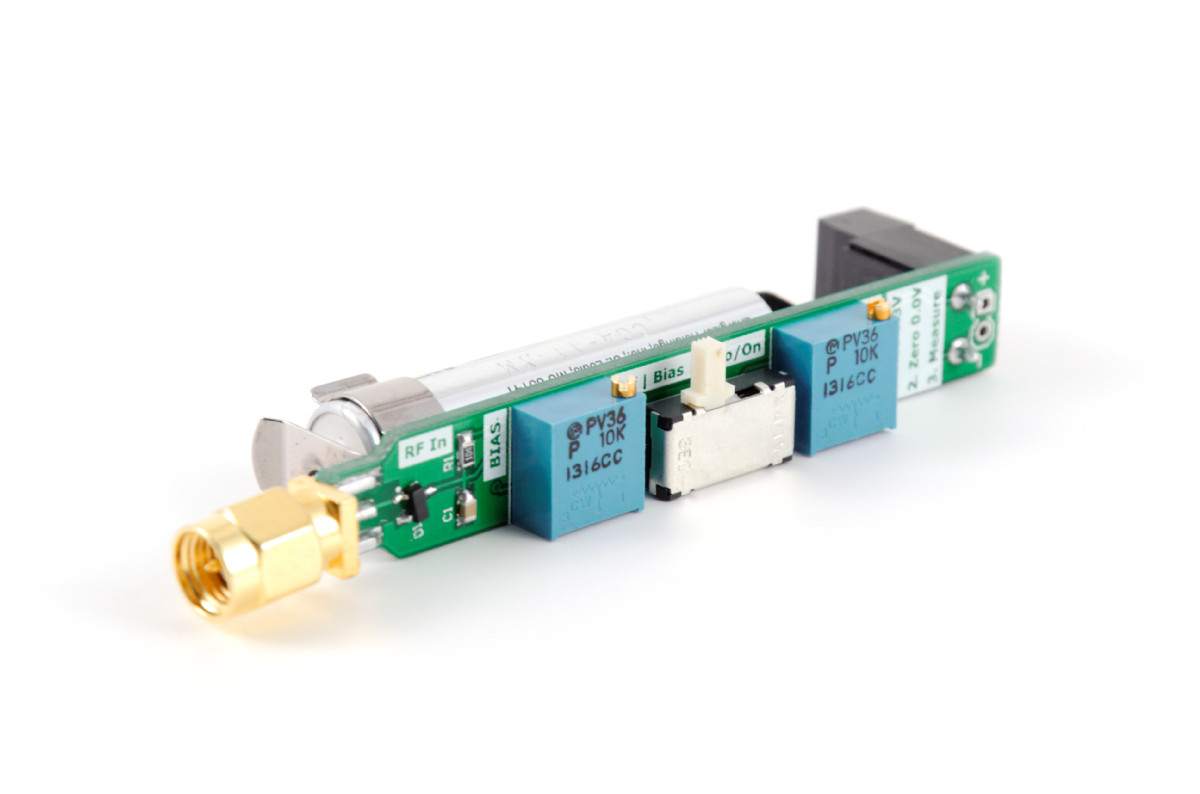
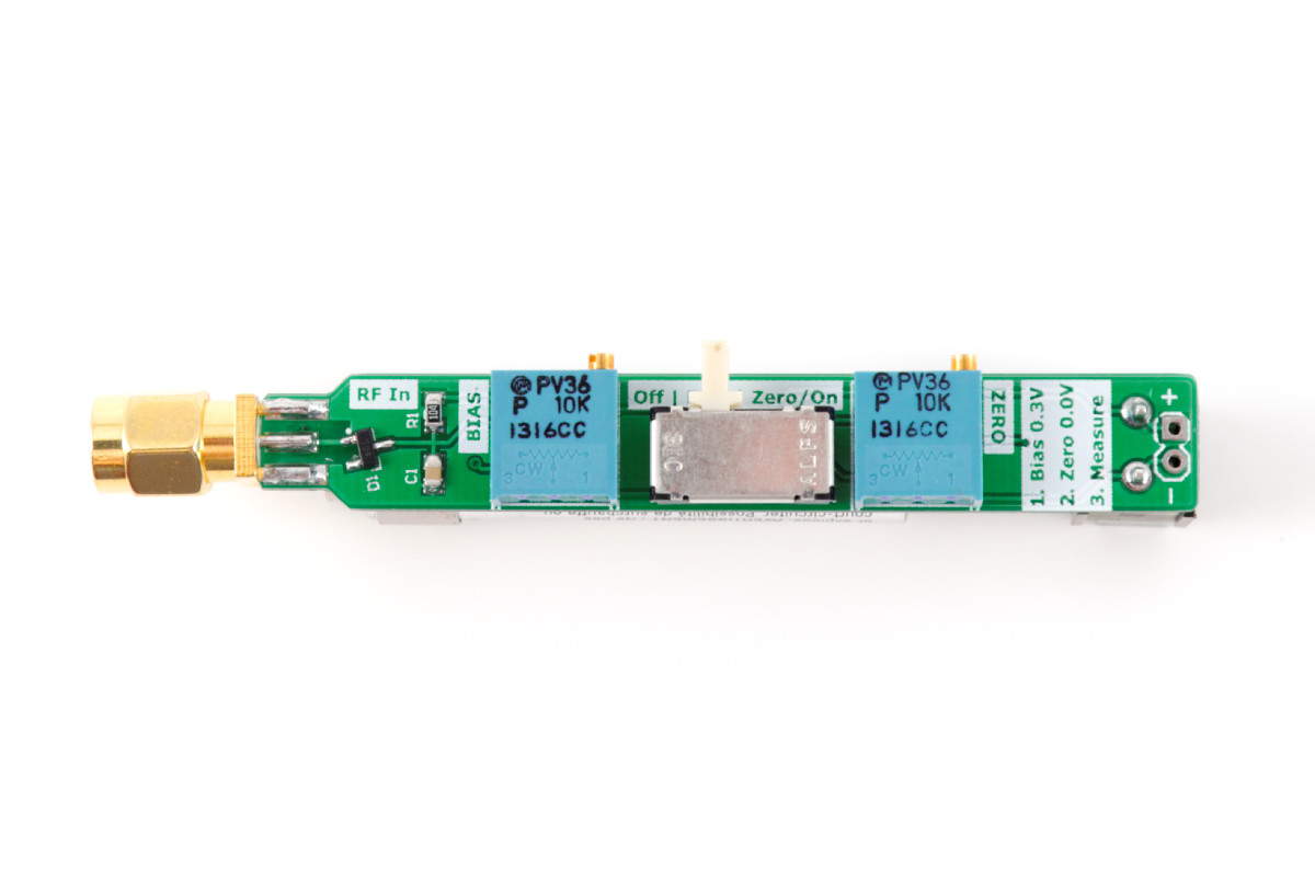
The detector is user calibrated using a 3-position slide switch (Off, Bias, Offset) and two multi-turn potentiometers (Bias, Offset); the DC bias pot will raise the voltage to "pre-activate" the diode and the zero offset pot will reset/null the output. The detector voltage is then measured using a multimeter on the therminal block or header. It is designed to work with a -10 dB coupler and an accurate 50 Ohm terminator.
It works perfect with 915MHz to 5.8GHz transmitters, with input sensitivity from 10mW (-10dBm) to 500mW (27dBm). Input over 500mW should be lowered using 3db/6dB/10dB attentuator(s) between the transmitter and the coupler to get it within the mentioned range, otherwise the rectifier diode will burn out.
The schottky diode is a Avago Technologies HSMS-2860-TR1G single RF detector. Input plug is a SMA male plug (non-RP). Recommended directional coupler can be found used (Ebay, Aliexpress) by searching for "coupler 10 db sma ghz", make sure the desired frequency range is covered. A terminal block make it easy to hook up multimeter probes or wire extensions.
Battery not included.
Based on IBCrazy's and Mictronics' design.
- SWR Meter Project - FPVLAB
- SWR Meter - DIY Project - RCGroups
Step-by-step instructions:
- Connect RF detector with a battery mounted to the FWD/coupled port on the coupler and the 50 Ohm terminator to the REF/isolated port, disconnect any transmitter or antenna
- Hook-up multimeter (DMM) to "+" and "-" to RF detector DCV output and set the multimeter dial to 2DCV range to get good resolution
- Set the RF detector switch to "BIAS" position
- Adjust the "BIAS" potentiometer with a small screwdriver until the readout on the multimeter equals 0.30V
- Next, set the RF detector switch to "Zero/on" position - the battery should be mounted the entire time
- Adjust the "ZERO" potentiometer until the readout is reset to 0.00V
- Repeat step 4 to 6 - the last adjustment can have a small effect on the first BIAS adjustment
- Now, connect the transmitter to the IN port and the antenna (DUT) to the OUT port on the coupler - with the RF detector still connected to the FWD, 50 Ohm terminator to the REF port
- Power on the transmitter and move away from the antenna (and keep the antenna away from metal objects), make a note of the multimeter readout (Vforward)
- Swap the coupled output ports to measure the reflected energy - move the RF detector from FWD/coupled to REF/isolated and 50 Ohm terminator from REF/isolated to FWD/coupled port, make a note of the reflected energy (Vreflected)
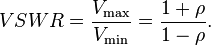
- Use the formula below to calculate the VSWR and use the table to get an idea how efficient your setup is
Specifications
- Product ID: RFD-02
- Revision: Rev3 Feb 2014
- Type: RF Detector with DC bias and Zero offset
- Frequency range: 915MHz to 5.8GHz
- Input power: -10dBm (10mW) to +27dBm (500mW)
- Sensitivity: -32dBm (diode capable of -55 to -57dBm)
- Forward bias current: 3uA (100k shunt resistor, equals +0.3V bias)
- Detector output voltage: +0.1-4.0V (max.)
- Connector type: SMA male (center pin, non-RP) 50 Ohm
- DC supply voltage: +1.0 to 1.8V
- Battery slot: AAA LR03/HR03 1.25-1.50V
- Dimensions: 71.48 L x 10.58 W x 11.0 H mm
- Weight: 13 grams (excl. battery
- RoHS compliant
- Designed and made in Europe
How to calculate VSWR
The principle is to connect the RF Detector to the coupler's Vreflected port and measure the voltage using a multimeter, then measure the Vforward port, and calculating the SWR to get a ballpark figure of how efficient your antenna is performing (input power).


Percentage losses:
| SWR Reading | Power loss | Output to antenna |
| 1.0:1 | 0.0% | 100.0% |
| 1.1:1 | 0.3% | 99.7% |
| 1.2:1 | 0.8% | 99.2% |
| 1.3:1 | 1.7% | 98.3% |
| 1.4:1 | 2.7% | 97.3% |
| 1.5:1 | 3.0% | 97.0% |
| 1.6:1 | 5.0% | 95.0% |
| 1.7:1 | 6.0% | 94.0% |
| 1.8:1 | 8.0% | 92.0% |
| 2.0:1 | 11.0% | 89.0% |
| 2.2:1 | 14.0% | 86.0% |
| 2.4:1 | 17.0% | 83.0% |
| 2.6:1 | 20.0% | 80.0% |
| 3.0:1 | 25.0% | 75.0% |
| 4.0:1 | 38.0% | 62.0% |
| 5.0:1 | 48.0% | 52.0% |
| 6.0:1 | 55.0% | 45.0% |
| 10.0:1 | 70.0% | 30.0% |